
After successfully making some simple FET probes I got interested in a differential probe as well. This is considerably more tricky to DIY than a single ended probe, and reaching 100MHz or so with classic thru-hole components is difficult if not impossible. So, I gave up on this until I saw a probe design by user Bud Benett on Hackaday. I asked the inventor if he would make me a probe if I pay for it (my eyes and hands are too old for 0604 parts), but he declined. Another user, Christoph, stepped in and agreed to do all the very small stuff and the soldering. We modified the orignal design by adding regulators, some offset circuitry that can be set from outside, and a LED lighting circuit with a slide switch. Christoph did all the PCB design using KiCad, and after some weeks a a nice probe arrived at my desk.
Measurements
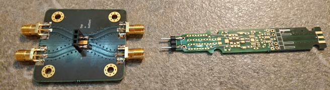
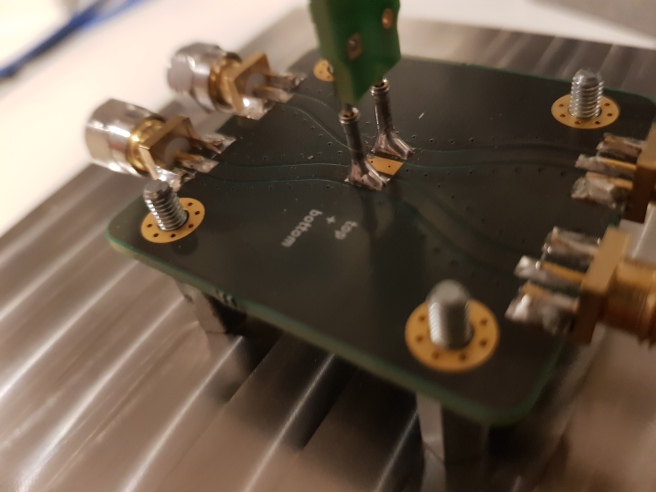
The prerequisite number one for probe measurements is a defined environment. Nobody can make reliable RF measurements of (proposedly) high impedance stuff without a stable geometry that keeps stray capacitances constant. So, the first step is a test fixture. It consists of a solid V2A steel block (that does not topple over when some heavier RF cabling is attached to it), a tower that holds the probe in clamps (printed on my 3D printer after a design by Christoph), and base plate where the input signals can be attached by SMA connectors and the probe tips by pinheads and sockets. The PCB of this is shown below:
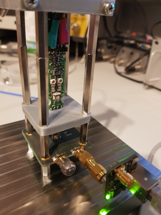
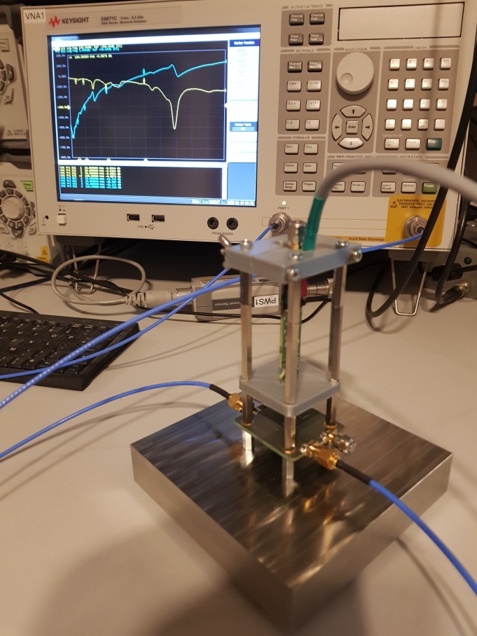
And the whole arrangement is here (you also see a pulser attaghed for risetime measurements):
Transfer Curve, Linearity, CMRR
DC Testing comes first. What we would need to know is a transfer curve (showing the clipping limits) and the DC CMRR of our probe. These values are extracted using a precision voltage source (in my case, a dual channel Keysight B2902A SMU), plus an accurate multimeter. For the transfer curve, one channel is held at zero volts, while the other is stepped from negative to positive maximum. This curve is shown here:
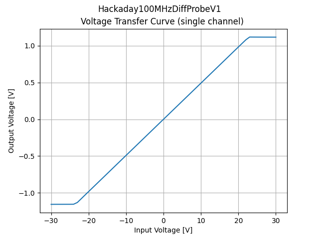
This is very close to the data advertised by the HackADay team (linear range +/-24V).
Next, we would like to see how well common mode signals are supressed. For that, we apply the same voltage to both SMU and probe channels and do the stepping in the same sense as before. Ideally, we should receive zero volts, in practice a small signal will appear. The amplitude of this unwated output divided by the input gives the CMRR at DC, as shown here:
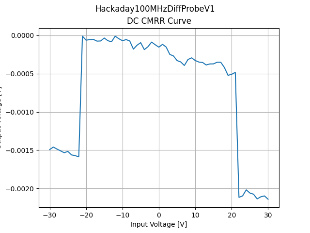
OK, does not look to bad at all. From -20V to +20V we see a variation of just 500uV, which is not a real problem (Christophs finetuning seems to have been very good, we are at almost 50dB). Next, we need to check dynamic characteristics.
Rise and Fall Times
We start with rise and fall times. A 100MHz probe should have rise and fall times in the ballpark of ca. 3.5ns. This value is below or at least in the same order of magnitude of the rise and fall times of standard function generators (Rigol DG1062Z: ca. 8ns, Tek 2535: ca. 3ns). This means that the measurements with standard equipment will be fairly inaccurate (the effect can be somehow calculated back, but with some error propagation). The best way is to measure with a signal source and a scope with risetimes of 1/10 of the device under test. To do this, I chose a Leo Bodnar Pulser (rise/fall times around 40ps) and a Keysight 6GHz scope, shown here:
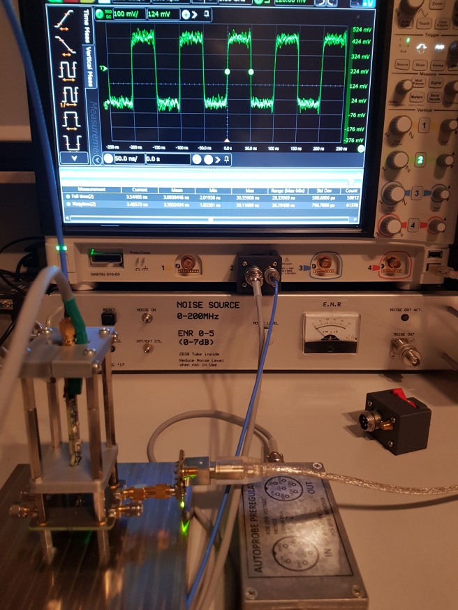
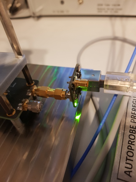
As you can see, the probe is powered by the scope using my hombrew Autoprobe adapter emulating a Keysight N2792A 200MHz probe´. The attached pulser is shown below (USB powered, with the green LED on):
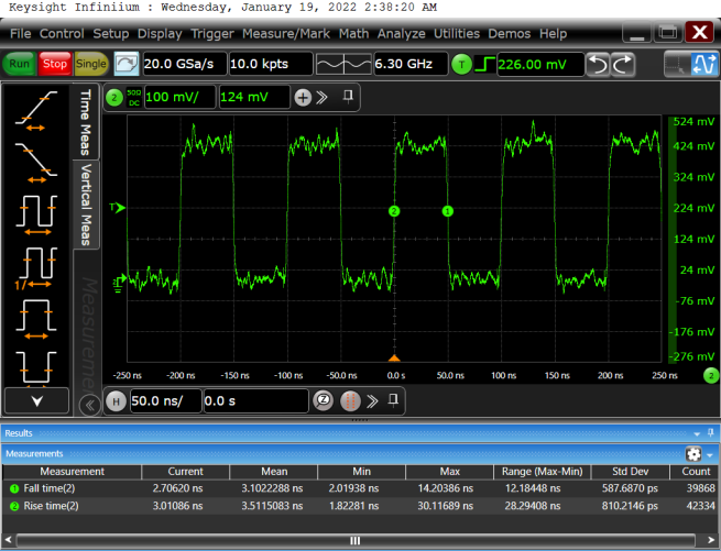
Measured risetimes of the probe were around 3.5ns, confirming the design:
We could verify our test fixture plus the probe on a VNA as well. In order to do this, we connect the VNA to the test fixture base plate and measure reflection and transmission thru the plate (this shows if the probe causes significant loading to the transmission lines and if the coupling between the striplines is low enough):
Results show that up to 100MHz we have no problem with probe inducted attenuation or coupling:
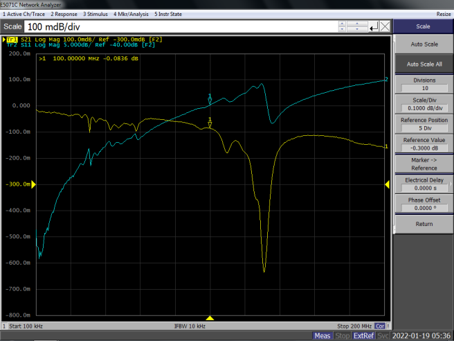
This is the baseplate thru measurement. Up to 100MHz, insertion loss is 0.1dB and refletion is below -25dB. Forward coupling (one stripline in the other is out) is shown here:
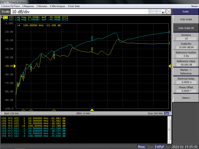
Well, we have -33dB at 100MHz, so no worry. Reverse looks similar:
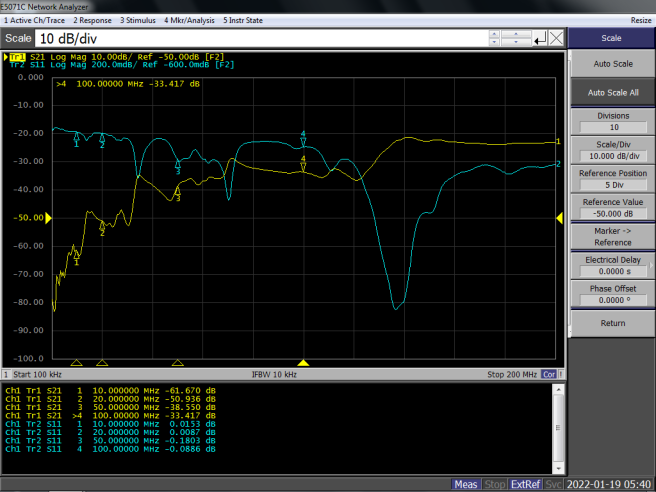
Next, we attach the VNA input signal to the baseplate PCB and we measure transmission at the probe output (we do this on one line only, the end of this line and both ends of the other stripline are terminated with 50Ohms). We can now see that we have a fairly flat curve that drops by some 3dB when approaching 100MHz, like here:
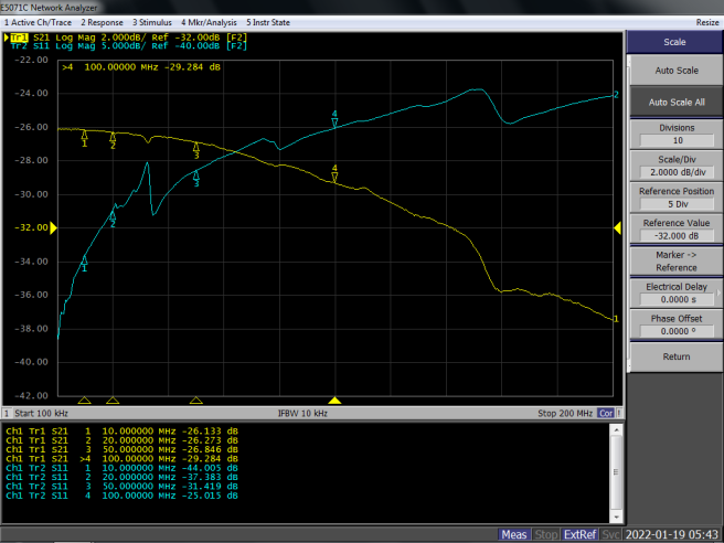
Looks pretty, and fairly flat up to 100MHz. Good agreement with rise and fall time measurements.
Supplying Power to the Probe
The probe itself has connectors to a +/-5V Line, ground and offset adjustment. I made an adapter to get this from the Keysight Autoprobe socket available on my scope. For more info, see my pages about using the Keysight Autoprobe interface in your own projects, like here:
Using the Keysight AutoProbe Interface in Your Own Projects
Autoprobe is not a must, however. You may also supply probe power using batteries or other sources. Offset is tuned by proving a current of up to +/-1mA at the probe offset pin. If you do nothing (leave offset open) a small DC offset (some mV) might appear at the output.
Next Steps
First, we need some more measurements (dynamic CMRR, capacitances, …), but we would also need a probe housing before we can expect reliable results there.
The housing is in the making, but Christoph made me a CMRR test fixture base plate I could use in my test setup, shown here:
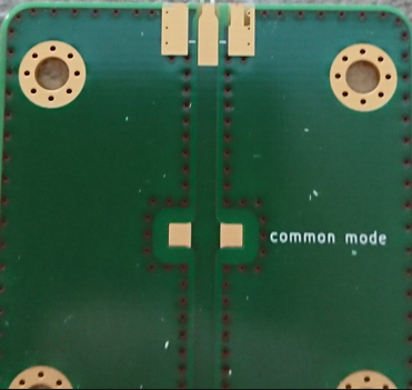
This drives both pins at (hopefully) the same signal because of the inherent symmetry. What we would expect is a high CMRR (at least at low frequencies). To check that we attach a VNA at one end of the baseplate, a termination resistor at the other and the probes output port goes to the VNA input. Here we are:
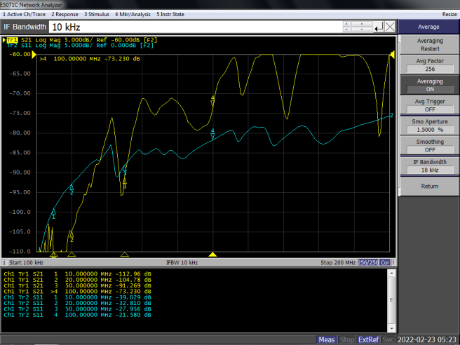
What we measure is the output signal with a common mode drive. We would need to subtract the differential probe gain from that to get the CMRR. Probe gain at low frequencies is -26dB (1:20), as shown above. So we start at a CMRR of around 80dB below 20MHz, deteriorating to ca. 50dB at 50MHz and ca. 44dB at 100MHz. This behaviour is to be expected and also shown by commercial probes. While the low end can be fiddled, stray capacities and unsymmetries place a principal limit to the achievable high frequency CMRR performance. We are still without a case, and even waving your hands around the probe will cause a few dBs up and down. With a proper metal housing, this wont happen.
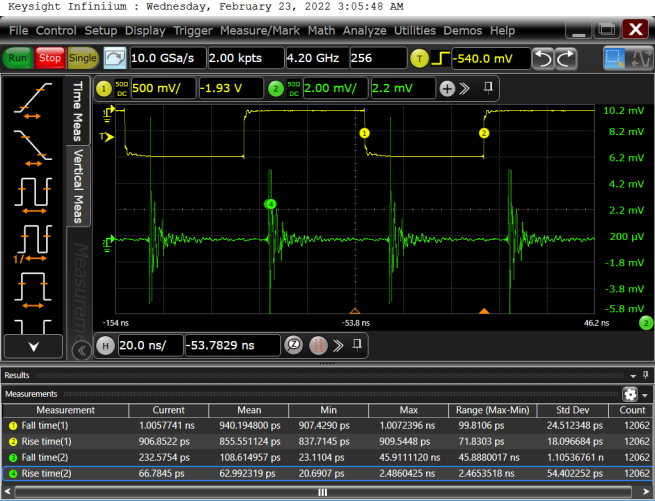
What CMRR (or the lack of) does to signal integrity can be shown using a pulser. If we reconnect our 40ps Bodnar pulse to both probe inputs, what comes out looks somewhat disturbing:
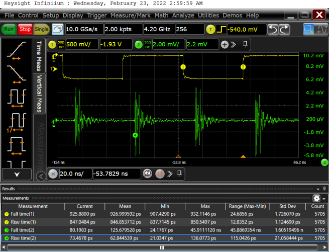
Well, actually its not that bad. We are running at 10MHz, the risetimes of the Bodnar pulser look OK (we have a 4.2GHz bandwidth limit active). The DC (or LF) symmetry is quite good (only a very small submillivolt offset is present), but at the corners there is a larger dynamic asymmetry,. resulting in error amplitudes of a few millivolts for an almost 1V input step. For a homebrew, this can be considered acceptable. Again, touching the probe even at the top SMA can change the waveforms considerably, so a proper case is a must. With a hand on the connector, we have this:
As can be seen spike shapes and amplitudes changed quite a bit, to prove the point.
The next step is to wait for Christophs new probe case made from milled Aluminium (whew !!) and then repeat the measurements.
Another point I found was that my own probe power supplies were a lot quieter than the Keysight scope outputs. This is no surprise because they use low noise LM723 stablizers with filtered references.
