
I already built a SCPI-enabled RF attenuator from old HP parts (probably removed from a spectrum analyzer). This works fine from 0-4GHz and is quite precise, to 0.1dB. The downside is that it only has 5dB attenuation steps, from 0 to 145dB. What I needed for some RF projects was an attenuator in 1dB steps, with a maximum range of 150MHz and a good accuracy at low frequencies.
Of course, you could again buy some HP parts and repeat the trick of my first attenuator. But – in the meantime these parts will drain your wallet by hundreds of €, even for a used eBay item. So, I opted to homebrew this.
Design
My attenuator consists of 6 Pi sections, with attenuations of 1,2,3,6,10 and another 10dB, giving a 32dB range. The sections are activated by Omron G6K-2PY subminature relays. All sections use classic 0.6W metal film resistors, with paralleled E24 values to give a 1% match of the exact value needed for the attenuation desired. This is a lot more power than standard 1207 SMD resistors could provide (I guess around 20dBm max.)
The values are:
A conservative power limit would be 1W/30dBm. Due to the THT design attenuations of more than 10dB tend to get isolation problems, and it makes sense to use smaller sections in series.
The relays are controlled using an Arduino Leonardo or Micro. Relay current is amplified by an ULN2003 driver. The complete unit is USB powered.
SCPI Control
The following specific SCPI commands are available:
:ATTN value
:ATTN:INCR
:ATTN:DECR
:ATTN?
:ATTN:RAMP
Some standard commands are also supported (*IDN?, *RST, *CLS, …). RAMP steps the attenuation up and then down from 0 to 32dB in 1s intervals. This is nice for testing. To avoid overloading while switching the relays from one value to another relays are always switched in first, then the relays of the old value no longer needed are switched off. There is a settling time (20ms) to make sure that a contact has been made/opened before the next relay is handled, so there is a lot of clicking …
First Results
A first version of the PCB had the relay coils … on a different ground than the RF side. This did not work so well, probably due to coupling capacitances within the relays. Having everything on one ground worked nicely, however. VNA curves can be seen here, S11 first, from the low attenuation side:

This looks so lala, with S11 better than 13dB everywhere, at all attenuations and at all frequencies. Below 30MHz, we are at 20dB or better.
S21 looks more pleasant:

The drop between 0 and 200MHz is no more than 1.2dB at 200MHz, and at 100MHz we have less than 0.52dB. DC is spot on, at (measured on a SMU/DMM combo) 0.15dB max. deviation.
Conclusions
The part does what it should do, i.e. provide accurate attenuation at up to 50MHz and usable values up to 200MHz. The interior can be seen here:
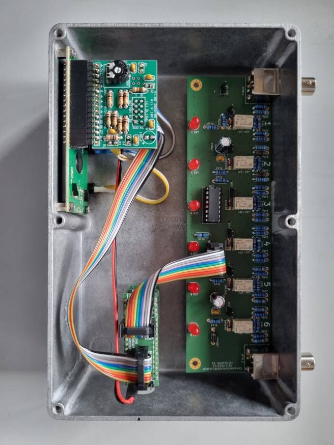
To the upper left we have the LCD display, the attenuator board sits on the right side, and at the bottom we have an Arduino Micro with a shield. Total cost is about 100€.
