

Update: I added a link to power supply flicker noise measurements
Update: I added a link to a good video from Goran Dzambazov how not to run an LM723 from zero volts like often cited from an old Elektor publication (***). Elektor after some decades responded to the criticism and explained how the blunder happened …
Update: I added a footnote with some info about LM723 vendors today (**)
Update: A schematic with all suggestions implemented can be seen at the bottom of this page.
Update: EEVBlog member Cody Turner sent me a datasheet and application note of the uA723 from 1968 !! Thanks, Cody !!
Update: I added a reference study that compares voltage regulator noise.
Update: EEVBlog Member Noopy created some chip photographs of different LM723 versions. Nice ! http://www.richis-lab.de/LM723.htm
Click here for a uA723_Application_Note from 1968 …
The LM723 is a classic, now available for 50 continuous years and still going strong. Naturally, it is frowned upon by a lot of designers that are just half as old. They see this chip as an old-age part that has no merits today. On the other side, it even made it into Horowitz and Hill’s Art of Electronics Version 3 in 2015. I have read dozens of forum discussions about the LM723 and its antiqueness (*).
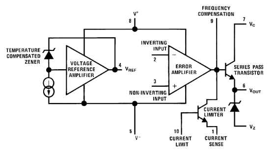
The interior design of an LM723 looks like this:
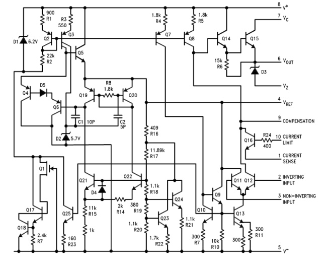
On a transistor level, you can see some design tricks by the legendary Bob Widlar :
If we pragmatically summarize the pros and cons of this methusalem, we end up with something like this:
Pros
- Proven. No wonder after 50 years, it is known what you may expect and what not.
- Stable. Relying on a buried Zener low noise reference, it can compete with a lot of newer chips when it comes to stability (it does have a long term stability rating in the datasheet, few new chips have that). Tempco is also very good, also when compared to newer chips.
- Low Noise. One of the best low noise regulators even today (when hooked up properly). Reason one is the low noise buried Zener reference, reason two is the fact that the reference voltage can be noise filtered before going into the error amp. Jörn Bartels DK7JB did a very good comparative study of different voltage regulators. It can be found here.
- Wide voltage range. Input voltage goes up tp 40V constant, with 50V pulses allowed. There is even an (obsolete) 80V version, the L146CB.
- Support for external pass transistors, keeping on-chip dissipation (and therefore drift) low.
- Compensation by the user. You can tailor the frequency response to your application (but you also have to do that because there is no internal compensation).
- Very flexible. Can serve as positive, negative, shunt, pass, floating or switching regulator or as a temperature controller.
- Extended Temperature Range available. You can get CDIP14 chips with an operating temperature range from -55°C to +125°C.
- Cheap. A few 10 €Cent, and its yours (the commercial version, that is).
Cons
- Complexity. People used to 3-terminal regulators are in for a culture shock caused by the amount of design aspects to consider. The LM723 is not as foolproof as an LM317 or LM7805.
- Not a very high PSRR. The PSRR is only a few ten dB, deteriorating with higher frequencies. If you want top performance, you need to supply a separate, ripple free supply for the error amp (V+).
- Inexact current limiting. The current limiting feature is implemented as a transistor that is turned on by the voltage drop on a current sensing resistor. This has the disadvantage of a lot of wasted power and voltage headroom, and the “knee” current has the 2mV/°C tempco of a Silicon BE junction.
- Current limiting sensitive to overload. If you have a heavily overcompensated (i.e. low speed design) and no base protection resistor at the LM723s CL/CS current limit transistor, this transistor can burn out before the slow regulator had the chance to drive output voltage down sufficiently.
- Minimum dropout voltage is ca. 10V. This is due to the 7.5V buried Zener reference. If you need to regulate lower voltages, the LM723 chip itself needs a separate power input at 10V minimum.
- Minimum regulated output voltage is ca. 2.5V (minimum allowed voltage for the error amp input). With less accurracy, you may go below that, but not by much.
- Moderate error amplifer gain. We have only a factor of ca. 33dB here, newer chips can easily have gains of 40-60dB. The LM723 values translate to about 0.03% of load regulation.
- Error amp bias current. The superbeta bipolars in the error amp have a low, but nonzero bias current that can cause voltage shifts of a few millivolts across voltage divider or RC filter resistors.
- Intolerant to missing or misdesigned compensation. Yes, it will oscillate if you forget or undercompensate.
- Be cautious when driving MOSFET pass transistors. Some extra bleeders are needed to make falling edge output regulations fast enough. Gate parasitic suppression resistors of a few 100 Ohms are also a good idea.
- No microscopic SMD cases available. The cases I know are PLCC20, TO5-10 metal can, SOIC-14 SMD and DIP14 in plastic and ceramics (LM723J military grades).
723 Design Rules Cookbook
So, in case you have decided for an LM723 to make a good power supply, there are some rules of thumb that will make your life easier:
- Filter the reference. Use an RC filter before feeding the reference voltage to the error amp. This also acts as a soft start feature.
- Equilibrate bias currents. Take all networks into account, and make sure that the reference divider and the output sampling network present the same impedance to the error amplifier inputs. This cancels the error amps base bias currents.
- Kill ripple (and if you can, also other voltage variations) at the V+ chip power supply. This can be done by a cheap LM78LXX preregulator or a capacitance multiplier circuit. The collector voltage (Vc) driving the output does not need to be stabilized.
- CL/CS Protection. If you use current limiting, protect the base of the limiting transistor by a (1K, e.g.) resistor.
- Keep cool. Although the LM723 can dissipate a few 100mW and deliver up to 150mA, better use an external pass transistor to do the hard work and keep the regulator chip cool. A PNP pass transistor can further improve noise performance.
- Provide enough voltage headroom. Even if the V+ is ca. 10V or more, the difference of Vc and output should be that the output transistor never approaches VceSat. This wastes some power, but speed, noise and other performance criteria are a lot better with a few volts across the pass transistor.
- Compensate properly. Before you specify a compensation cap, run a few tests using SPICE to see if gain and phase margins are in order. Try with different output voltages, load currents and input voltages.
- Minimum output current. The LM723s output stage is a NPN Darlington that can drive current, but not sink any current. Especially when driving MOSFETs, you might need a bleeder resistor to make the falling edges fast enough for your needs.
- Minimum Output for Floating Regulators. The datasheet is not very instructive on this, but the floating regulator variants will fail to regulate when the load resistance becomes to high. The load must be able to drain at least the supply current of the 723 circuit without exhibiting a voltage higher than the desired output voltage.
- If you want precision current control, dont try to do this with a pot sampling a fraction of voltage across a shunt measurement resistor. The CS/CL mechanics is strictly to prevent meltdown, but never for an accurate current control function. The curves of the limiting transistors Vbe voltages over temperature in the LM723 datasheet should make it absolutely clear that no precision can be expected here. The way to go is either high side sensing with an op amp that can do that, or a floating design like the famous Elektor one from 1982 (1 x LM723, 2 x LM741).
- Observe the minimum voltage at the error amplifier inputs. “Regulate down to zero” solutions published are normally flawed. Even circuits with a crude negative supply voltage to offset the 2V minimum are often just very bad designs (***).
A schematic where all this has been implemented can be see below:

Click here for a larger resolution picture …
A lot of basic application circuits can be found in the LM723 datasheet. The net and some manufacturers application notes are also a good source of information.
Click here for an LM723 Datasheet from Texas Instruments …
Exotic Uses of the LM723 Regulator
Just in case you’re interested in a bit arkane circuitry using an LM723 – here is one. Its a self-heated reference.
Click here to see a Self-Heated LM723 Reference …
Other pranks to follow when they run over my desk.
Measurements of LM723 Regulator Output Noise
Some measurements of linear regulator low frequency noise can be found here:
The Good, the Bad and the Ugly
The LM723J performs flawlessly !
(*) These forum discussions about the LM723 routinely follow a standard pattern:
User A : How could you ever think in 2018 of designing with such an outdated / obsolete / discontinued / antique / bad performance IC ? The XYZ IC is so much better in all respects !
User B : When you ask for the same basic parameters (40V, 150mA, …) there is simply no better IC today. There are only better ones with low voltage (10V and less), and they cost a lot more than a LM723. Its comparing apples and oranges.
User C : The LM723 is not discontinued at all, sold by TI in the millions, available from all electronic distributors and dirt cheap.
User D : The performance of an LM723 is not bad at all, especially for noise and long term stability. Which comparable ICs are so much better now ?
User A : Silence or no reply.
(**) Since the last update, some market changes occurred that are relevant to the availability and quality of some LM723 circuits. First, ST went out of the LM723 business. They dont make this part anymore. As I found out (and others did as well) their consumer parts where a bit drifty (within spec limits), probably by a conversion to a new manufacturing process with not just improvements as a consequence. For your bread-and-butter PSU, they are still fine and noise is quite low.
Second, TI bought the inventor of the LM723, National Semiconductor. Both have been making 723s for decades, and after the sale TI took over the National Semiconductor designation of LM723 and used their own of uA723. LM723 parts were shown as discontinued, but uA723 parts are still available in PDIP, CDIP and TO-99. From a power supply manufacturer I read some email correspondence with TI tech support where he also claimed more drift in recent parts. After some ping-pong TI recommended the MIL-spec part and guaranteed that this would be free from drift.
(***) A very nice video from Goran Dzambazov about a famous but misdesigned Elektor circuit allowing you to run an LM723 with an output voltage from zero Volts can be see here:
Click here to see a video of how not to make an LM723 power supply starting at 0V
Some wonders come (very) late. Elektor magazine has now responded to this video
https://www.elektormagazine.com/news/0-30v-ua723-based-regulated-power-supply
and admitted the English article was bullshit. It appears that the original article in Dutch was OK, but the translator got carried away with superlatives …
If Elektor tries to sell you a design as “laboratory”, “precision”, … a grain of salt is always a good idea. In case of the misdesigned power supply, the simplistic solution with a temperature-unstable Zener diode could be replaced by a better source of negative voltage – what about another LM723 🙂

need schematic for Tripp-Lite PR7
LikeLike
… what is a Tripp-Lite PR7 ? Found it on the net, we dont have it here in good old Europe. No schematics either, I’m sorry.
LikeLike
I think most of the discussion of the 723 comes from one common misconception:
It is and stays a great part to build a precision low noise fixed voltage source with overload protection. But it does not well apply to an universal laboratory power supply with adjustable voltage and current limit.
LikeLike
Agreed. Whats mssing is a precision limiting mechanism. The CS/CL protection helps against DUT total failures, but its not good for precisely setting current.
LikeLike
Please don’t accuse the Elektor’s translators, they do not add anything to an article (in fact they are always trying not to lengthen the size of it). Clemens Valens knows, who posted Elektor’s reply to the video, knows that and he specifically blamed the publisher of the UK edition of the magazine.
LikeLiked by 1 person
OK, then its the UK publisher of Elektor. Not speaking Dutch, I have to rely on the English (or German) language translations.
Regarding the design, even a cheap TL431A instead of the Zener would have improved a lot of the problems (temp dependency, ripple).
Thanks for your comment
Wolfgang.
LikeLike
Hello,
if you look for exotic LM723 applications, some years ago I ran into one in an old East German book,”Harro Kühne: Schaltungspraxis für Meßgeräte”. He used the MAA723 (Czechoslovakian clone) as a rail splitter to create a virtual ground for an opamp application.
The schematic was dead-simple. The MAA723 was set up as a 14.3V (2 * Vref) power supply, powering an opamp. The reference voltage output Vref (7.15V) of the MA723 was then used as virtual ground for the signal input and output of the opamp. So the signal was biased right in the middle of the opamp’s power supply.
LikeLiked by 1 person
Hi Old Guy,
that definitively works, but the reference voltage output cannot supply more than 10mA. If the op amp circuitry is OK with that, why not ?
Buffering the reference with a cap also reduces noise. I found this book in my library. If you mean the circuit on page 12, terminal 4 is virtual ground, but the Op amp supply voltages are unsymmetric, -7.2V and ca. 14.3V, so its not the middle. The circuit works anyway.
regards
Wolfgang
LikeLike